
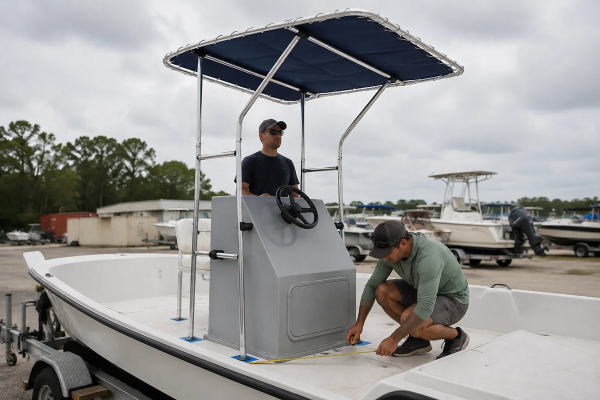
Cover image note: This AI-generated technical illustration shows a representative center-console T-top dry-positioning check. It is not a vessel-specific fit approval; verify structure, clearances and measurements on the actual boat.
A center-console T-top must fit three spaces at once: the console, the people using the boat and the structure below the deck. A product can clear the console and still be wrong because its feet land on weak or inaccessible areas, its braces block movement, or its canopy interferes with electronics.
Draw the installation envelope
Make a simple plan view of the console and deck. Mark the narrowest and widest console dimensions at the heights where uprights may pass. Add wheel, throttle, doors, cup holders, side access panels and any handrail. Then record the available deck footprint on both sides.
Use removable tape to mark proposed feet. Check that every location is flat enough for the base and that a tool and backing arrangement can reach from below. A liner gap is not automatically structural support.
Measure people, not just fiberglass
Have the tallest regular operator stand at the helm and move through normal steering and throttle positions. Check:
- head clearance beneath frame and accessories;
- shoulder and elbow clearance beside uprights;
- the path from cockpit to bow;
- sightlines seated and standing;
- access to fire extinguisher, electrical panels and console doors;
- boarding and emergency movement.
Look above and below before drilling
Above, map antennas, navigation lights, rod holders, speakers and the sweep of rods. Consider where water will drain from the canopy. Below, inspect wiring, fuel-system components, hoses, core and access. If you cannot verify the drill path and structural support, do not drill.
The AirowMarine center-console T-top is one product form. Its live dimensions and supplied instructions—not the article photograph—must be compared with your measurement drawing.
Rigidity comes from geometry and attachment
Tube diameter alone does not determine stiffness. Span, bracing, joint design, base spacing, fasteners and deck structure all contribute. Do not force uprights apart or together to reach marked feet; stored stress can distort the frame and load the deck. Assemble and square the structure according to the manufacturer's sequence.
Installation-day stop points
- Dry-assemble enough of the frame to confirm real outside dimensions.
- Recheck console doors, steering, throttle and passage.
- Confirm all four mounting areas and below-deck access.
- Verify the drill path independently at each foot.
- Stop if the deck flexes, core is wet, wiring cannot be moved safely or the feet will not sit flat.
After installation
Inspect bases and joints before the first run. Test at conservative speed within the product instructions, then recheck for movement, fretting, fastener changes and canopy tension. Add electronics only within the maker's permitted loading and routing provisions. Reinspect after trailering as well as after running, because the load direction is different.
Reference boundary: Measurement and installation sequencing were cross-checked against the Fishmaster Pro Series installation manual. Follow the instructions supplied with your selected T-top; fastener, backing and operating requirements are model-specific.


Leave a comment
This site is protected by hCaptcha and the hCaptcha Privacy Policy and Terms of Service apply.