
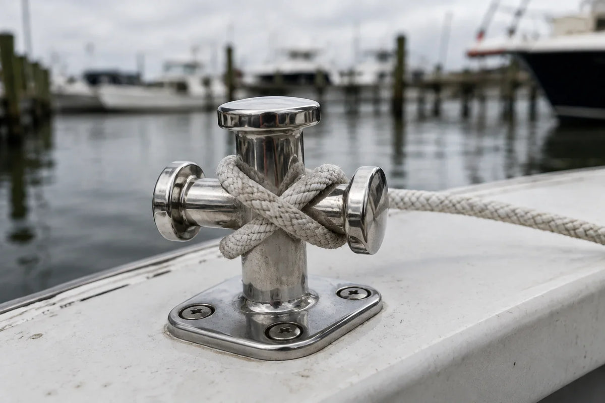
Cover image note: This AI-generated technical illustration shows a reference-based cross-bit bollard with a dock line. It is not proof of backing strength or a customer installation; inspect the structure below the deck.
A mooring cleat is only the visible end of a structural system. The line loads the horns, the body loads the fasteners, the fasteners load the backing, and the backing spreads that force into the deck or gunwale. If any link in that chain is weak, a larger or shinier cleat does not solve the problem.
Read the line lead before choosing a fitting
Stand where the boat will actually be tied. Note whether the line approaches forward, aft, outboard or upward, and whether a fairlead or chock changes that direction. A cleat needs enough clear horn length for the intended line and enough surrounding space to make a proper turn without trapping fingers.
Also examine what happens when the boat moves. A line that looks fair at rest may bear against a rail, rub a gelcoat corner or lift the cleat during surge. Chafe protection belongs where the movement occurs; it should not be used to disguise a poor lead.
The mounting surface is part of the specification
Before ordering, determine:
- the flat footprint available on top;
- deck or gunwale construction and thickness;
- whether the laminate is cored and, if so, the condition of the core at existing holes;
- access for nuts, tools and a backing plate;
- clearance below for bolt ends and nearby wiring, hoses or trim;
- the existing hole pattern and whether old holes are sound.
Softness, brown water, crushed core or an enlarged hole changes the job from hardware replacement to structural repair. That repair should be designed for the boat's construction and expected loads.
Why a backing plate matters
A backing plate spreads load across a larger, sound area and helps reduce local crushing. Its material, thickness, footprint and edge treatment need to suit the substrate and environment. A small washer may be acceptable for some low-load fittings, but it should not be assumed equivalent to a designed backing plate for mooring hardware.
BoatUS illustrates the general distinction in its guidance on backing plates and provides a practical overview of cleat installation. Those resources are useful context, but the final structure remains vessel-specific.
Cleat, folding cleat or bollard?
A conventional horn cleat is easy to recognize and tie. A folding or low-profile cleat can reduce snagging when not in use, but adds a hinge or moving mechanism that must remain clean and fully deploy. A cross-bit bollard offers a different wrapping geometry and footprint. Choose by line handling, load path, deck space and service access—not appearance alone.
Examples in the AirowMarine catalog include an inset folding cleat, a low-profile horn cleat, and a single cross-bit bollard. The product pages are form-factor references. Do not infer allowable mooring loads from size or material name; confirm documented ratings and the boatbuilder's requirements.
A cautious installation sequence
- Dry-fit the cleat and simulate the line leads with the intended rope.
- Mark holes, then inspect the drill path from below.
- Prepare existing or new penetrations using a method appropriate to the deck construction.
- Use compatible fasteners and a designed backing arrangement. Avoid creating galvanic couples without considering isolation and drainage.
- Bed penetrations with a sealant compatible with both materials and future service needs.
- Tighten evenly without crushing the laminate or squeezing out all bedding.
- After cure, inspect below while the fitting is loaded progressively in a controlled setting.
Inspection tells
Movement rings in dirt, cracked bedding, dished laminate, gelcoat cracks radiating from holes, fretting beneath washers and rust tracks from hidden fasteners all deserve investigation. Photograph a clean baseline after installation. At later inspections, matching camera angles make small changes easier to see.
Safety boundary: Mooring hardware sees dynamic loads that vary with vessel displacement, wind, waves, line elasticity and geometry. This article does not calculate a safe working load or certify an installation. Use vessel-builder guidance or a qualified marine professional where the load path is uncertain.


Leave a comment
This site is protected by hCaptcha and the hCaptcha Privacy Policy and Terms of Service apply.