
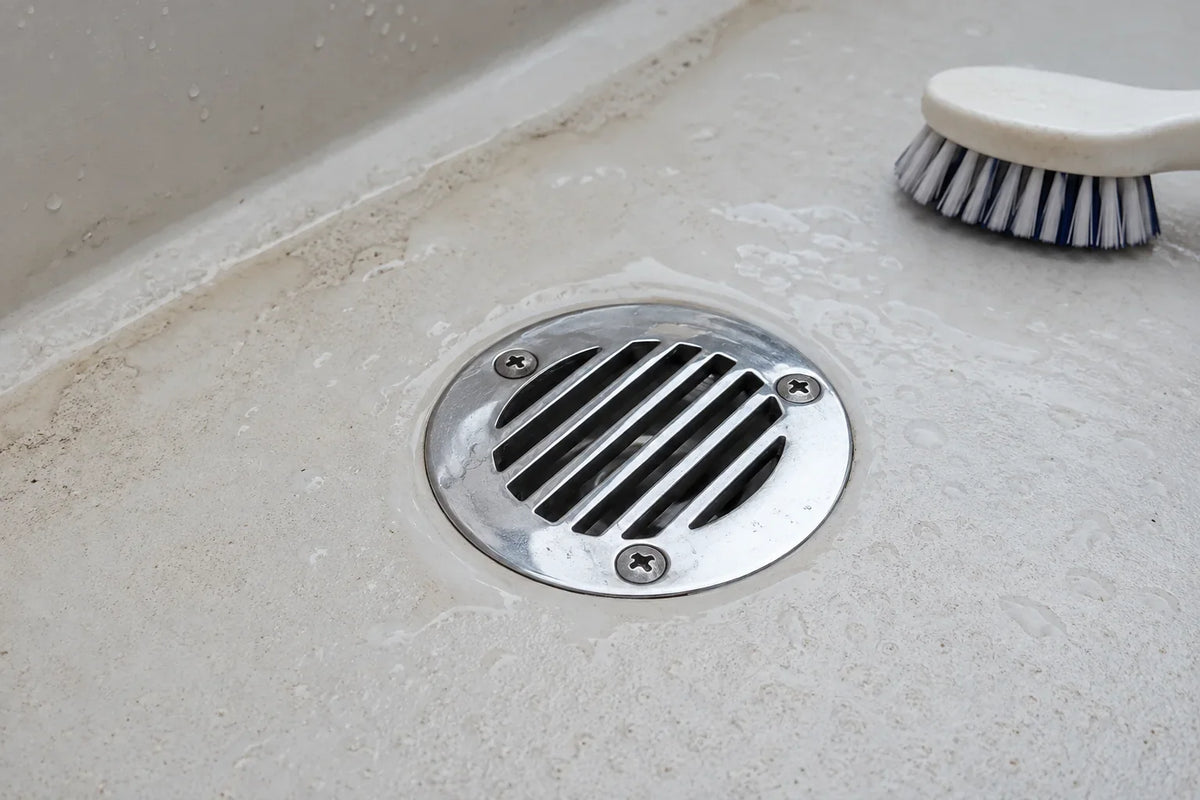
Cover image note: This is an AI-generated technical illustration of a representative deck-drain inspection, created from product references. It is not a customer boat photograph or evidence of a completed AirowMarine installation.
Safety note: A hull penetration or failed drainage connection can admit water into a boat. Location relative to the waterline, applicable standards and vessel-builder instructions must be confirmed before installation. Use a qualified marine installer for below-waterline and safety-critical work.
A deck drain is not just the polished fitting visible under your shoe. It is the beginning of a path: water crosses a grate or opening, enters a body, passes through a hose or molded channel, and exits through a discharge fitting. Depending on its location, a valve or anti-reflux device may also be part of the system.
Choosing only by flange diameter or material leaves too many unanswered questions. A good replacement has to fit the deck, preserve drainage capacity, connect to the correct hose, remain accessible and comply with the requirements that apply at its installed height.
First, name the component correctly
Product names overlap in everyday use, so confirm what each part actually does.
- Deck drain
- A fitting that collects water from a deck, cockpit or floor and sends it into a hose or drainage channel.
- Scupper
- An opening or fitting intended to let water drain from a deck or cockpit, often overboard.
- Thru-hull fitting
- A fitting that passes through the hull so liquid or gas can enter or leave through connected pipe or hose.
- Seacock
- A valve attached to a hull penetration so the flow can be shut off when required.
- Check or anti-reflux valve
- A device intended to reduce reverse flow. It is not automatically a substitute for a seacock where a seacock is required.
- Garboard drain plug
- A removable drain normally used when the boat is out of the water. It belongs to a different operating routine from a cockpit scupper.
A product can combine several functions, but the listing must be checked rather than inferred from the name.
Map the complete drainage path
Before removing the old fitting, trace the system from the deck opening to the discharge. Photograph every connection and record:
- What area the drain serves.
- Whether the opening can ever be at or below the maximum heeled waterline.
- Existing flange, cutout, thread, barb and hose dimensions.
- Deck thickness and available space below the fitting.
- Hose type, internal diameter, route, bends and vertical rise.
- The outlet location and orientation.
- Any seacock, check valve, strainer or manifold in the path.
- Access for installation, inspection and emergency operation.
Do not assume an existing installation is correct merely because it has not failed yet. Previous owners may have mixed incompatible threads, used ordinary plumbing components or routed hose where it can kink or retain water.
Location relative to the waterline changes the decision
A fitting high on the hull that discharges a bilge pump does not face the same flooding risk as a penetration below the maximum heeled waterline. The American Boat & Yacht Council lists separate standards for cockpit drainage, bilge pumps, water systems, seacocks, thru-hulls and drain plugs. ABYC guidance cited by BoatUS states that a hull penetration designed to accept a pipe, hose or valve, with any part of its opening below the maximum heeled waterline, should have a seacock capable of stopping water admission if the connected system fails.
That distinction cannot be decided from a product photograph. Vessel loading and heel can place an apparently “above-waterline” fitting closer to the water than expected. If there is uncertainty, confirm the maximum heeled waterline and applicable standard with the builder or installer.
Seven measurements to take before ordering
- Visible flange diameter: Will it cover the existing opening and bedding footprint?
- Required cutout: Is the deck opening compatible without removing excessive structure?
- Body depth: Is there clearance below the deck for the body and connection?
- Outlet size: Does the hose fit the actual barb or threaded adapter?
- Outlet direction: Can a straight or 90-degree outlet align without forcing the hose?
- Fastener pattern: Do holes align, and is there sound material or backing beneath them?
- Service clearance: Can clamps, strainers, removable grates and valves be reached later?
Use the dimensional drawing for the exact variant. Nominal “38 mm” or “1.5 inch” wording may describe a hose connection, pipe, cutout or another feature. It does not prove that every dimension is interchangeable.
Choose the drain form around the available space
Low-profile or tubeless deck drain
A low-profile fitting can be useful where depth is limited and the deck construction already provides a suitable discharge path. The 76 mm tubeless 316 stainless deck drain has a listed flange of approximately 75.6 mm and overall depth around 29 mm. “Tubeless” describes the product form; it does not make the fitting universal. Confirm the cutout, deck thickness and path below it.
90-degree hose outlet
A right-angle body may help where a straight outlet would collide with structure or require a tight hose bend. AirowMarine’s 90-degree stainless floor drain is offered in integral and detachable 32 mm and 38 mm variants. Select the variant from actual connection dimensions and the service access needed, not from the article title.
Larger outlet and removable grate
A 50 mm deck drain may provide a larger connection than smaller models, but “high flow” in a product name is not a system flow rating. Real drainage depends on the smallest restriction, grate area, head, hose length, bends, outlet position and maintenance condition. Use calculated or tested data where a minimum drainage rate is required.
Anti-reflux or ball-valve scupper
A 1.5-inch anti-reflux ball scupper is intended to reduce reverse flow in a compatible arrangement. Check orientation, fouling risk and inspection access. Debris, growth or damage can prevent a moving element from seating. It should not be treated as a permanent guarantee against backflow.
See the full plumbing and ventilation collection to compare listed configurations.
Material choice is only one layer
316 stainless steel is frequently selected for exposed marine fittings because it generally resists chloride-related corrosion better than 304. It can still stain or corrode in crevices, beneath deposits or where dissimilar metals and electrical conditions are unfavorable.
A polished face says nothing about thread compatibility, backing, hose quality or the condition of the deck core. The fitting, valve and connected components should use materials suitable for the installation. Avoid casual combinations of metal and composite threaded parts; their thread forms, stiffness and thermal behavior may differ.
For a deeper material comparison, read 304 vs 316 stainless steel vs galvanized steel for marine hardware.
Hose and clamp details deserve the same attention
A good fitting cannot protect a cracked hose or misplaced clamp. Choose hose approved for the fluid, temperature, pressure or suction, bend radius and waterline location involved. Cockpit drainage hose and engine exhaust hose do different jobs.
The hose should reach the connection without being stretched, crushed or forced into a kink. Support long runs and protect them from abrasion. On a beaded or serrated hose tail, the clamp belongs in the designed clamping area rather than hanging off the hose end.
ABYC’s public hose-clamp guidance explains that H-27 requires sufficient hose-tail length and space to position the specified clamp beyond the bead or over the serrations. Requirements vary by system, so consult the current standard and the exact component instructions instead of copying a universal “one clamp” or “two clamps” rule from a forum.
Installation sequence
The exact procedure depends on the vessel and fitting, but a disciplined workflow looks like this:
- Haul or secure the boat as required for safe work on the penetration.
- Close and verify relevant seacocks; control any possible water path.
- Photograph and label the existing hose and component orientation.
- Remove the old fitting without enlarging or damaging the opening unnecessarily.
- Inspect the laminate, core, backing and bedding surface for moisture or damage.
- Dry-assemble the complete path and verify thread, hose and access compatibility.
- Use bedding compound appropriate to the substrate and fitting material.
- Install backing and fasteners according to the builder or component instructions.
- Fit the correct hose without twist or excessive bend and position clamps correctly.
- Allow sealant to cure as specified, then test and inspect the installation.
Do not use sealant to compensate for damaged laminate, mismatched threads or poor mechanical support. If the fitting serves a below-waterline opening, a qualified installer should verify the complete assembly.
Commissioning and leak checks
Test the drainage route before normal operation. Introduce water to the served deck area in a controlled way and watch the grate, hose, joints and outlet. Confirm that water does not pond because of trim or an obstructed channel.
After launch, inspect every disturbed hull connection immediately and again after the boat has operated. BoatUS recommends checking thru-hulls for leaks after launching. Operate accessible seacocks through their full range and confirm that handles are not blocked by equipment or stored gear.
If a check or anti-reflux valve is present, test both forward drainage and the conditions that could create reverse flow. Never assume the moving element is clean and free simply because it worked when new.
Routine inspection checklist
- Remove leaves, line fragments, scales and other debris from grates.
- Check that water drains freely with the boat at its normal trim.
- Inspect bedding seams for cracking, movement or staining.
- Look for corrosion, impact damage and distorted fastener holes.
- Feel hoses for hardening, soft spots, cracking and kinks.
- Check clamps for corrosion, correct position and security.
- Exercise seacocks and verify that they remain accessible.
- Clean and inspect check-valve or ball components where serviceable.
- Confirm that modifications or stored equipment have not blocked the flow path.
Symptoms that call for investigation
- Water remains on deck longer than it used to.
- The cockpit drains differently to port and starboard.
- A hose collapses, surges or moves during drainage.
- Odor or water returns through the drain.
- Rust-colored staining, green deposits or dampness appears around a fitting.
- A seacock is stiff, inaccessible or its open/closed position is unclear.
- The outlet submerges under loading or heel conditions not previously considered.
A larger fitting is not automatically the answer. The restriction may be elsewhere in the hose or outlet, and enlarging a deck opening may create structural or sealing work. Diagnose the complete path first.
What AirowMarine needs for a fit discussion
Send the existing fitting photographs, flange and cutout measurements, deck thickness, hose internal diameter, outlet direction, installation height relative to the waterline, and the AirowMarine product link. We can compare those details with listed product dimensions. Final compliance and installation suitability must be confirmed for the vessel.
Technical references
- American Boat & Yacht Council: standards list, including H-4 and H-27
- ABYC: hose clamps, thru-hulls and seacock hose connections
- BoatUS: seacock selection, access and inspection
- BoatUS: choosing hose for different marine systems
- BoatUS: inspection of cockpit drains, thru-hulls and seacocks
Standards change and some full ABYC requirements require licensed access. Use the current applicable edition and the instructions for the exact vessel and components.



Leave a comment
This site is protected by hCaptcha and the hCaptcha Privacy Policy and Terms of Service apply.