
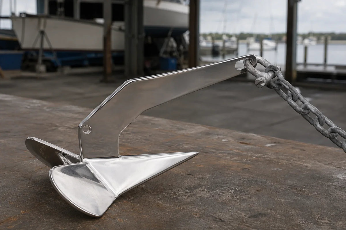
Cover image note: This AI-generated technical illustration shows a simplified ground-tackle connection based on product references. It is educational, not proof of a specific installation; component ratings and maker instructions still control.
Safety note: Anchoring is a system-level and seamanship decision. Use the vessel builder’s guidance, the equipment manufacturer’s instructions, local regulations and a qualified marine professional where necessary. This guide does not assign an anchor size or safe-weather limit to a particular boat.
An anchor is easy to photograph because it is the most recognizable part of ground tackle. It is also only one link in a longer chain of decisions. The anchor has to suit the vessel and seabed. The rode has to provide the right geometry and shock behavior. The chain has to fit the windlass gypsy. Shackles and swivels have to fit physically and carry the intended load. The bow roller, stopper, cleat and locker have to guide and secure the system without introducing a new weak point.
When a ground-tackle setup disappoints, the cause is often not a single “bad anchor.” It is a mismatch somewhere between these components or between the system and the conditions in which it is being used.
Think in systems, not shopping lists
A useful way to specify ground tackle is to work from the boat outward:
- Vessel length, displacement, windage and bow arrangement.
- Operating area, expected depth, tide, current and weather exposure.
- Likely seabed types and local restrictions.
- Primary and secondary anchor strategy.
- Chain, rope or combination rode.
- Shackles, swivels, thimbles and splices.
- Bow roller, windlass, chain stopper, cleat and locker.
- Deployment, setting, securing, retrieval and inspection procedure.
This order prevents a common mistake: buying a polished anchor first, then trying to make the existing roller, windlass and locker accept it.
Step 1: describe the boat and the job
Length alone is not enough. Two boats of the same length can have very different displacement and windage. A high-sided powerboat, a low-profile center console and a cruising sailboat will not load their ground tackle in the same way. Start a selection worksheet with:
- Length overall and displacement in normal cruising condition.
- Hull type, freeboard and structures that add windage.
- Day anchoring, overnight cruising, fishing, emergency use or storm preparation.
- Typical and worst credible water depth, including tide.
- Expected bottom: sand, mud, clay, weed, gravel or rock.
- Available swinging room and proximity to other vessels or hazards.
- Existing bow roller, windlass, locker and securing points.
Manufacturer sizing charts can provide a starting point, but the inputs and assumptions behind one chart may differ from another. If the intended use includes exposed overnight anchoring or unusual vessel windage, ask the anchor and vessel manufacturer for guidance rather than treating a generic length-to-weight table as a guarantee.
Step 2: choose anchor geometry for the likely bottom
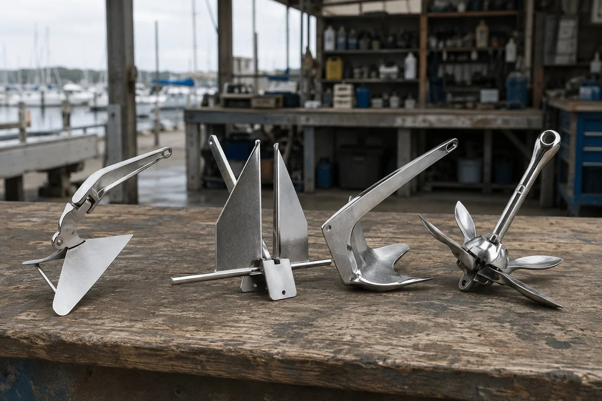
Anchor families solve the same problem in different ways. Broad-fluke anchors can perform well in compatible sand and mud. Plow and claw-style anchors are widely used because they can be practical across several bottom types and stow conveniently on many bow rollers. Grapnel and small folding anchors are compact but belong to different use cases from a primary cruising anchor.
BoatUS notes that boat type, bottom composition, wind and water conditions all matter when choosing an anchor. That is more useful than declaring one geometry universally best. The right comparison is between exact models, sizes and test conditions, not between marketing adjectives.
AirowMarine’s anchoring and docking collection includes several geometries. The 316 stainless delta-style anchor, for example, is available in multiple weights, but weight alone does not establish suitability. Confirm the dimensional drawing, roller fit and the manufacturer or designer’s size guidance for the vessel.
Step 3: decide what the rode must do
The rode connects the boat to the anchor and determines the angle at which load reaches it. Common arrangements include all-chain rode and a chain-and-rope combination. Each has trade-offs in weight, abrasion resistance, shock absorption, handling and locker requirements.
Chain near the anchor resists seabed abrasion and adds weight low in the rode. Nylon rope can add useful elasticity to absorb changing loads. An all-chain setup commonly uses a separate snubber to introduce elasticity and transfer load to a suitable strong point. The exact arrangement must suit the boat, windlass and intended conditions.
Scope is measured from the seabed to the bow roller
Scope is the length of deployed rode divided by the vertical distance from the seabed to the point where the rode comes aboard, not merely the charted water depth. BoatUS uses approximately 5:1 as a minimum starting point for secure anchoring and notes that 7:1 can be preferable where room permits. Those figures are guidance, not a universal safe value. Tide, waves, current, bottom, rode type and available swinging room can require a different decision.
A skipper should calculate the high-water depth, add bow-roller height, allow enough rode, and verify that the resulting swing circle is safe. In crowded or environmentally sensitive areas, local rules and mooring options may control the choice.
Step 4: match chain to the windlass, not just by diameter
“8 mm chain” is not a complete windlass specification. Link pitch, width and manufacturing standard affect how the chain sits in the gypsy. Lewmar’s windlass manuals list particular chain standards and dimensions for each gypsy. A chain that is nominally the same diameter but has the wrong pitch can climb, skip, jam or wear the gypsy.
Before ordering a 6 mm or 8 mm calibrated short-link anchor chain, record the windlass make, model, gypsy number and the exact chain specification it accepts. If those details are unavailable, measure a known compatible sample and consult the windlass manufacturer. Do not rely on diameter alone.
Also check that the rope-chain splice, if used, is compatible with the gypsy and can pass through the deck pipe. The locker must be deep enough for the rode to fall away from the gypsy without piling up and feeding back into it.
Step 5: treat connectors as part of the load path
Shackles and swivels are small enough to be treated as accessories, but their geometry and rating matter. Check all of the following:
- The pin passes through the anchor shank or chain link without side loading.
- The body clears the bow roller, stem and windlass path.
- The connector has a traceable rating appropriate to the system.
- The pin has a suitable method of security and remains accessible for inspection.
- Adjacent components do not create an unfavorable metal combination.
- The swivel, if used, is installed in the orientation specified by its manufacturer.
A 316 stainless bow shackle with safety bolt and nut is available in several nominal sizes. A 316 stainless anchor swivel is another possible connection method. Neither should be selected from nominal size or appearance alone. Confirm dimensions, material, rating and compatibility with the exact chain and anchor.
Step 6: make the bow hardware work as one path
During recovery, the anchor has to arrive at the roller in a predictable orientation, pass the stem without striking the hull, and seat without placing an unintended load on the roller or windlass. Check:
- Anchor shank length, fluke clearance and resting position.
- Roller width, diameter and material.
- Alignment from roller to gypsy and from gypsy to locker.
- Mounting footprint, fasteners, deck structure and backing.
- A separate way to secure the anchor for travel.
- A chain stopper, cleat or other designated strong point for anchoring load.
The 715 mm stainless anchor bow roller is one available configuration, not a universal fit. Compare its drawing with the anchor, stem and mounting area before ordering.
Windlass manufacturers warn that the windlass should not be used as the boat’s mooring point. Lewmar instructs users to secure the rode independently to a cleat, chain stopper or other designated strong point. That protects the windlass drivetrain and transfers the sustained load to hardware intended to carry it.
Step 7: set the anchor and prove the set
A careful installation can still be defeated by a poor set. A general sequence is:
- Check depth, tide, swing room, bottom information, wind and nearby traffic.
- Prepare the anchor and rode while keeping people, loose clothing and lines clear of moving equipment.
- Lower the anchor under control rather than throwing it and fouling the rode.
- Pay out rode as the boat moves back, avoiding a pile directly on top of the anchor.
- Apply load gradually in accordance with the equipment instructions to help the anchor set.
- Use visual transits, depth, chartplotter information or an anchor alarm to confirm whether the boat is holding.
- Transfer the load from the windlass to the intended strong point.
Conditions can change after the first successful set. Reassess when the tide turns, wind shifts or the boat begins to swing differently. In protected or sensitive seabed areas, follow local anchoring restrictions and use designated moorings where required.
Inspection: pull out enough rode to see the hidden parts
A glance at the anchor on the roller does not inspect the system. Periodically deploy or lay out the rode in a controlled location and examine:
- Anchor deformation, cracking, welds, casting surfaces and corrosion.
- Shackle bodies, pins, locking arrangements and elongated holes.
- Swivels for free movement, wear and manufacturer-specified orientation.
- Chain for distortion, severe corrosion, wasted links and damaged welds.
- Rope for glazing, hard spots, cuts, chafe and degraded splices.
- The bitter-end attachment and whether it can be released in an emergency.
- Rollers, pins, cheeks, windlass gypsy, stripper and deck fasteners.
- Chain stopper, cleat, backing structure and snubber.
Replace a questionable part based on its condition and the manufacturer’s criteria, not because the visible face can be polished. Safety-critical hardware deserves a conservative decision.
A one-page compatibility record
Keep the following record with the vessel documents:
| Primary anchor | Make, model, size, dimensions and stated application |
|---|---|
| Rode | Chain standard/size/length; rope material/diameter/length |
| Connectors | Type, dimensions, rating and pin-security method |
| Windlass | Make, model, gypsy number and approved chain specification |
| Bow hardware | Roller model, stopper, cleat and securing method |
| Inspection | Date, findings, parts replaced and next check |
This record makes future replacement easier and prevents a new chain, shackle or windlass part from being selected in isolation.
Technical references
- BoatUS: how to calculate anchor scope
- BoatUS: choosing an anchor for boat and bottom conditions
- Lewmar: V1–V3 windlass kits and downloadable product resources
- Lewmar: windlass and anchoring system layout
- Royal Yachting Association: anchoring and sensitive seabed habitats
External references provide general seamanship and equipment guidance. Always use the current manual for the exact anchor, windlass, vessel and operating area.

Leave a comment
This site is protected by hCaptcha and the hCaptcha Privacy Policy and Terms of Service apply.